Designing your Experiment
Please read this wiki page if you would like to run an MEG experiment at MCW. Here you will find information about the various stimulus presentation software available and information on setting up triggers for your experiment.
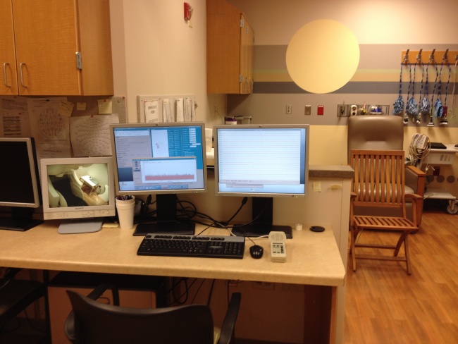
MEG Lab Components
- Stimulus presentation computer: Windows XP 2002.
- Analysis Computer: Windows 7
- MEG Neuromag Vectorview Acquisition System
- Optical response pad (Elekta Finger pad)
- Stimulus Trigger BNC Interface Units
- Polhemus Head Digitisation Unit
Scripting your Experiment
Your study experiment can be programmed using Presentation, Matlab, EPrime or Psychopy. Eprime, Matlab scripts can be written and executed using the Stimulus presentation computer kept at the MEG facility. Please call ahead, if you would like to schedule a time to use the stim computer to program your experiment.
Software
- Matlab R2007b Version 7.5
- Eprime EStudio Version 1 See EPrime for more information.
- Eprime 2 - Standard Version
- Stim2 from Neuroscan
- Presentation 11.3 (Please check with staff before programming)
- Psychopy
Stimulus Presentation
There are different ways of presenting the stimuli to your subjects, we will elaborate the systems we have at the facility here.
Visual
Projector and Screen
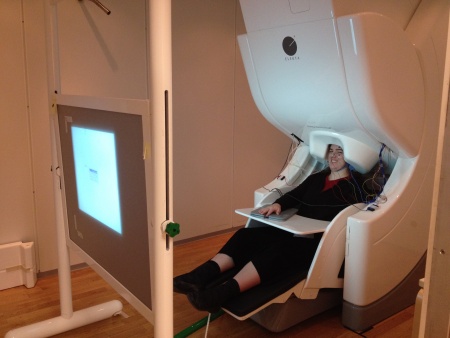
Visual stimuli are projected on to the screen inside the MSR using a Panasonic DLP Projector Model PT-D7700UK Manual projector that is housed outside the MSR inside the Helium tank room. The signal is projecting though a periscope into the MSR onto a back-projection screen that is placed in front of the chair. The optimal positions for the screen is marked by tape on the floor for correct focus. Please make sure to place the screen at these locations before your experiment and be sure to move it towards the wall after your finish. There is a small note on the screen showing which side should face the subject.
Delays
Photodiode test:
Using a light diode we measured a jitter of about 35.9 ± 0.4 ms between the trigger codes sent from the stimulus PC to the MEG acquisition computer and the visual output in the projector screen inside the MSR that the subject sees. These results were acquired for a specific setting and therefore the researchers are encouraged to conduct their own personalized tests. They are advised to simulate the same settings as their experiment and collect the data. The photodiode and related equipment to conduct the test will be provided.
Instructions for Projector
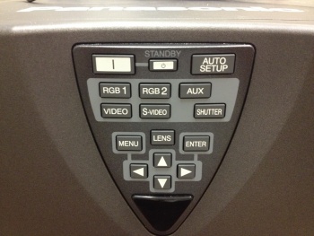
- Turn on the projector by using the switch on the left side of the projector and press the ON button in the main panel.
- Wait for a few seconds for the red light to turn Green.
Adjustments
- If the focusing, zooming or positioning of the image projected on the screen is not successful, even though the projector is properly positioned against the screen, you can adjust the focus, the zoom, or the vertical or horizontal position of the image.
- Click on the LENS button on the main panel or in the remote control and use the navigation buttons to adjust the focus, zoom and shift aspects.
Auditory
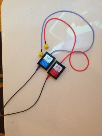
For delivering auditory input to the subjects in the MSR, we use a pair of MEG compatible Tubal Insert head Phones (TIP 300 - Nicolet). The use of Nicolet TlPs maximizes interaural stimulus isolation, prevents ear canal collapse, and reduces stimulus artifact. TlPs are easy-to-use, lightweight, durable and comfortable for the patient.
Use a new set of foam ear-tips for every subject. Attach the yellow foam tip to the tubes and hand it over to the subject. After use, throw away the yellow foam ear-tips, but make sure you do not dispose off the white plastic piece attached to the end of the tubes.
Triggers
During an MEG scan, stimuli from the presentation computer are presented to the subject seated inside the MSR (Magnetically Shielded Room) and the MEG signal is recorded on the acquisition computer simultaneously. As the stimuli are presented to the subject, a trigger pulse (digital pulse) is recorded along with the MEG signal in a separate channel and serves as a temporal marker. This is the STIM channel that contains information about the events/triggers such as start of the event, duration of the event and the event ID. These triggers are useful for time locking analysis of your MEG data such as evoked analysis etc.,
Stimulus Trigger Interface
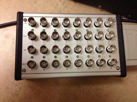
STI102
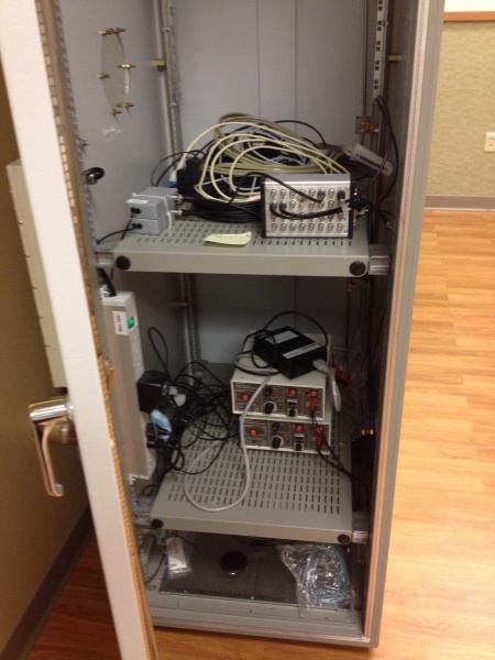
STI101 Inside the Triggers/Electronics Cabinet
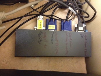
The digital triggers are sent from the stimulus computer through the parallel port to the Trigger Box - STI102 (Shown above) that is placed on the Stimulus presentation table. Any visual stimulus input from the Presentation computer is directly sent to the MSR via a relay device shown below.
The triggers sent by the computer are sent to STI102 that are directly fed to the Neuromag MEG Acquisition computer to be recorded along with the MEG signal collected from the subject seated inside the MSR.
Response Triggers
The responses collected from the subject using the Elekta optical response pads. These responses are encoded in the trigger box (STI101) via BNC cables, that is housed inside the Trigger Cabinet shown above and are recorded in the ST101 channel along with the stim triggers (STI102) and MEG signal data.
Trigger Settings
As we mentioned before there are two trigger units - STI101 (inside cabinet) and STI102 (stimulus computer table).
OPTION 1:
When the STI101 is not selected in the Acquisition settings, then the two trigger units operate in Parallel, or in 'Mirror' mode. So when STI102 receives a input in any of the IN pins, it is seen in the corresponding OUT pins of both STI102 and STI101 and in addition to this the signal is also sent to the STIM channel(STI102) to be recorded with MEG data.
OPTION 2:
When both STI102 and STI101 are connected - they act independently. But NOTE that any responses sent to the Trigger Unit STI101(inside cabinet) do not get sent to the stim computer.
Supplies
- 4 EEG 60 channel caps in 4 different sizes
- 1 set of Ambu Neuroline cup electrodes
- Ten20 conductive gel (electrode paste)
- Nuprep (skin preparatory gel)
- Cotton tips, tapes, gauze
- Electrode gel syringe (BD Diagnostics 5m)
- Blunt syringe tips (needles)
- Hand-Held Degausser (Geneva PF 215)
